Ahmedabad - 382430, Gujarat (India)
Printed Circuit Boards (PCBs) are the unsung heroes of modern electronics, silently powering devices from smartphones to spacecraft. At their core, PCBs rely on a carefully orchestrated ensemble of components, each contributing to the board’s functionality. However, the performance of a PCB hinges not only on the selection of these components but also on their precise placement, secure connections, and protection against issues like short circuits. This comprehensive guide explores the world of PCB components, offering insights into their roles, effective soldering techniques, and strategies to prevent short circuits. Whether you’re a hobbyist tinkering with DIY projects or an engineer designing cutting-edge technology, mastering these fundamentals will elevate your PCB projects to new heights.
This guide will walk you through the essentials of PCB components, from their basic functions to advanced assembly techniques. You’ll learn how to choose the right materials, identify and place components correctly, connect them seamlessly, and troubleshoot common issues like short circuits. By the end, you’ll have a solid foundation for creating reliable, high-performance PCBs that stand the test of time.
PCB components are the individual elements that bring a circuit board to life. Each component serves a specific electrical purpose, such as controlling current, storing energy, or processing signals. From the humble resistor to the sophisticated integrated circuit (IC), these components work in harmony to execute the tasks defined by the circuit’s design. Without them, a PCB would be nothing more than a lifeless slab of material.
Components vary widely in complexity and function. Some, like resistors and capacitors, perform simple tasks, while others, like microprocessors, handle intricate computations. The choice of components depends on the device’s requirements, whether it’s a low-cost consumer gadget or a high-reliability medical system. Understanding the role of each component is the first step toward building a functional and efficient PCB.
The foundation of any PCB is its material, which influences how components are mounted, how the board handles heat, and how it performs under stress. The most common substrate is FR4, a fiberglass-reinforced epoxy that offers a balance of strength, insulation, and affordability. For flexible PCBs, polyimide is preferred due to its bendability, making it ideal for wearable devices or compact electronics. In high-power applications, aluminum substrates excel at dissipating heat, protecting components from thermal damage.
The choice of material impacts not only the board’s physical properties but also its electrical behavior. For instance, FR4 provides excellent insulation, preventing unwanted current flow between traces, while polyimide supports dynamic applications where flexibility is key. Additionally, the solder mask—a protective layer applied over copper traces—shields components from environmental factors like moisture and dust. Selecting the right material ensures that components are securely mounted and that the PCB operates reliably under its intended conditions.
PCBs host a variety of components, each with a unique role in the circuit. Below, we explore the most common components and their functions, providing a clear picture of how they contribute to a PCB’s operation.
Resistors limit the flow of electric current, protecting sensitive components from overload. They’re essential in applications like LED circuits, where excessive current could cause damage.
Capacitors store and release electrical energy, acting like tiny batteries. They stabilize power supplies, filter out noise, and smooth voltage fluctuations in circuits.
Inductors store energy in a magnetic field when current flows through them. They’re commonly used in power supplies and radio frequency circuits to filter signals.
Diodes ensure current flows in one direction, safeguarding circuits from reverse voltage. They’re critical in power supplies and signal processing.
Transistors function as switches or amplifiers, controlling current flow based on input signals. They’re the backbone of digital circuits and amplifiers.
Integrated Circuits (ICs) are miniature powerhouses, combining thousands of components into a single chip. They perform complex tasks like data processing, memory storage, and signal modulation.
Transformers transfer energy between circuits via electromagnetic induction, enabling voltage conversion in power supplies.
Switches allow manual control of a circuit by opening or closing electrical paths, commonly used in user interfaces.
Voltage Regulators maintain consistent voltage levels, protecting components from spikes or drops in power.
Silicon-Controlled Rectifiers (SCRs) act as controlled switches in high-voltage applications, such as motor controls.
Crystal Oscillators generate precise clock signals for timing, ensuring synchronization in microcontrollers and communication devices.
LEDs (Light-Emitting Diodes) produce light when current flows through them, serving as indicators or displays in electronics.
Each component is carefully selected to meet the circuit’s electrical and physical requirements, ensuring optimal performance.
Identifying components on a PCB is a critical skill for assembly, repair, and troubleshooting. Most PCBs use a silkscreen layer to print reference designators—letters like “R” for resistors, “C” for capacitors, and “U” for ICs—next to each component. These designators, combined with part numbers or ratings, provide a roadmap for understanding the board’s layout.
For example, a resistor might be labeled “R1” with a value like “10k” (10,000 ohms) printed nearby. Capacitors may include capacitance values (e.g., “100µF”) or voltage ratings. ICs often carry part numbers, which can be cross-referenced with datasheets to confirm their function. During repairs, a magnifying glass or multimeter can help verify component identities, especially on densely packed boards. Accurate identification ensures that replacements or upgrades maintain the circuit’s integrity.
Effective component placement is a blend of engineering precision and practical considerations. Poor placement can lead to signal interference, overheating, or manufacturing challenges, while thoughtful placement enhances performance and reliability. Key principles include:
PCB design software, such as Altium or KiCad, allows engineers to simulate placements and optimize layouts before production. By balancing electrical, thermal, and physical constraints, proper placement ensures a robust and efficient PCB.
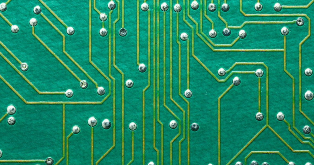
Components on a PCB are linked through a network of copper traces, vias, pads, and landings, forming the circuit’s electrical pathways. Copper traces act as conductive highways, carrying signals and power between components. Vias—small, plated holes—enable connections between layers in multi-layer PCBs, allowing complex circuits to fit in compact spaces. Pads and landings provide surfaces for soldering component leads, ensuring secure electrical and mechanical bonds.
Two primary mounting technologies dominate PCB assembly:
Advanced PCB design software simulates connections, catching errors like open circuits or incorrect routings before manufacturing begins. This ensures reliable connectivity across the board.
Short circuits are a common PCB failure mode, occurring when unintended connections form between traces, pads, or components. This can lead to malfunctions, overheating, or permanent damage. Common causes include:
Preventing short circuits requires diligence at every stage:
By addressing these risks, you can significantly enhance your PCB’s reliability.
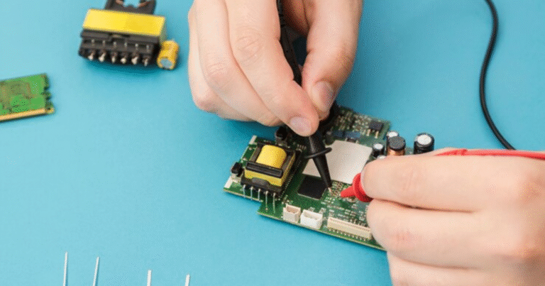
Soldering is the art of joining components to a PCB, and mastering it is essential for creating durable, functional boards. A well-executed solder joint ensures strong electrical and mechanical connections, while poor soldering can lead to failures. Here’s how to excel at soldering:
For advanced projects, explore techniques like drag soldering for multi-pin ICs, reflow soldering using solder paste and ovens, or hot air rework for surface-mount components. Practice and attention to detail will refine your skills, ensuring professional-grade results.
Selecting the right components is a critical step in PCB design, balancing performance, cost, and practicality. Key considerations include:
By carefully evaluating these factors, you can build a PCB that meets both immediate needs and long-term goals.
Mastering PCB components, soldering techniques, and short-circuit prevention is a journey that combines technical knowledge with hands-on skill. From selecting the right resistors and capacitors to perfecting solder joints and validating designs, every step demands precision and care. By understanding the roles of components, optimizing their placement, and safeguarding against issues like short circuits, you can create PCBs that are reliable, efficient, and built to last.
Whether you’re assembling a prototype in a garage or designing a commercial product, these principles will guide you toward success. At Megabyte Circuit, we’re committed to supporting your PCB projects with high-quality manufacturing and expert advice. Ready to take your electronics to the next level? Contact us today to bring your vision to life!
C/10, Yogeshwar Estate, B/H Madhuram Estate, Nr. Vishala Estate, Sardar Patel Ring Rd, Odhav, Ahmedabad, Gujarat, Ahmedabad - 382430, Gujarat (India)
Copyright © 2025. Megabytes Circuit Systems All rights reserved.
Powered by FrogMEE Tech